
Deploying Computer Vision on the Factory Floor: A Practical Pilot Framework for Manufacturers
A practical engineering guide for manufacturing and operations teams planning a computer vision pilot: hardware constraints, lighting consistency, edge inference, and training data quality.
The Serviceverse Engineering Team
Computer Vision & AI Systems
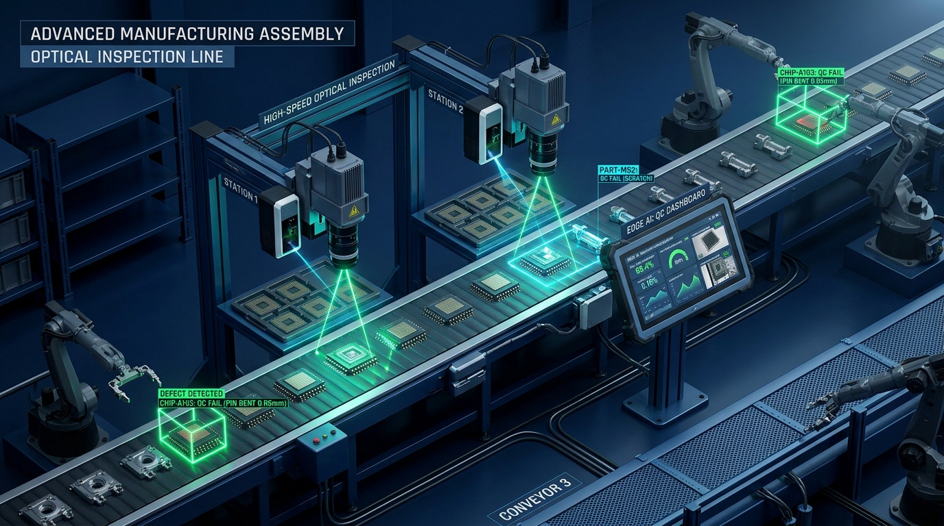
Automating visual quality inspection is one of the highest-leverage investments a manufacturing plant can make. Manual inspection is fatiguing, inconsistent across shifts, and increasingly expensive as production speeds climb.
Yet, a substantial percentage of industrial computer vision pilots fail to transition from a bench demonstration into 24/7 assembly line operations. The breakdown rarely stems from deep learning algorithms; modern convolutional networks (CNNs) and vision transformers (ViTs) are exceptionally capable. Instead, pilots fail because of environmental drift, edge latency constraints, and—most commonly—a complete misunderstanding of the training data required to catch rare manufacturing defects.
This guide outlines an engineering-first framework for planning, testing, and deploying a computer vision inspection pilot that survives factory floor realities.
---
1. The Factory Floor Reality vs. The Laboratory Demo
In a machine learning demo or a university benchmark, images are captured under consistent diffuse lighting with stationary parts against a clean background. On an operational shop floor:
- Ambient sunlight shifts from morning to afternoon through skylights, throwing dynamic shadows across metal surfaces.
- High-speed conveyor belts introduce motion blur unless shutter speeds and strobe lighting are precisely synchronized.
- Airborne dust, oil mist, and machine vibrations degrade optical lenses over 8-hour production runs.
- Defect classes are inherently unbalanced: 99.8% of produced parts are nominal, meaning standard data collection yields almost no images of actual structural tears, micro-cracks, or misaligned solder joints.
If your pilot does not account for these physical constraints before training a model, the system will achieve high accuracy on historical test sets while producing unacceptable false-reject rates in live production.
+-------------------------------------------------------------------------+
|                  PHYSICAL FACTORY ENVIRONMENT                           |
|  - Variable Ambient Light  - High-Speed Motion  - Vibration & Dust       |
+-------------------------------------------------------------------------+
                                    |
                                    v
+-------------------------------------------------------------------------+
|                    HARDWARE & OPTICAL STACK                             |
|  - Telecentric Lenses  - Strobe Illumination  - Industrial GigE Camera   |
+-------------------------------------------------------------------------+
                                    |
                                    v
+-------------------------------------------------------------------------+
|                     EDGE INFERENCE RUNTIME                              |
|  - ONNX / TensorRT Engine  - NVIDIA Jetson / Industrial PC (<15ms)      |
+-------------------------------------------------------------------------+
                                    |
                                    v
+-------------------------------------------------------------------------+
|                 PLC & REJECT MECHANISM INTEGRATION                      |
|  - Digital I/O (Optocoupler)  - Pneumatic Pusher / Diverter Gate        |
+-------------------------------------------------------------------------+
---
2. Four Optical Prerequisites Before Writing Code
Before selecting a neural network architecture, the physical imaging system must be locked down:
A. Lighting Geometry and Color Temperature
Lighting accounts for over 70% of inspection reliability. Standard overhead fluorescent or LED lights are inadequate:
- Directional Darkfield Lighting: Essential for detecting surface scratches, burrs, and engraving depth on reflective metal or glass.
- Diffuse Dome / Coaxial Lighting: Eliminates glare on specular surfaces like printed circuit boards (PCBs) or polished polymers.
- Backlighting: Ideal for profile inspection, edge burrs, and dimensional verification where internal surface details are irrelevant.
B. Industrial Cameras vs. Off-the-Shelf Webcams
Standard USB webcams utilize rolling shutters that expose pixels line by line, causing distorted images on moving conveyors. Industrial vision systems require global shutter sensors (transmitting via GigE Vision or USB3 Vision) that expose all pixels simultaneously, freezing motion without geometric distortion.
C. Lens Selection and Working Distance
Standard commercial lenses introduce radial barrel distortion at frame edges. For high-precision dimensional metrology, telecentric lenses are mandatory because they maintain constant magnification regardless of the object's distance from the camera within the depth of field.
D. Triggering and Synchronization
Software-based polling introduces variable latency. Industrial systems utilize hardware photo-electric sensors wired directly to the camera’s digital input pin (optocoupler trigger), firing camera capture and strobe illumination within microseconds of part arrival.
---
3. Edge vs. Cloud: Inference Latency and Architecture
A common architectural misstep is streaming video frames to a centralized cloud provider for inference. On an active packaging or stamping line running 300 parts per minute, each piece passes the inspection station in 200 milliseconds.
| Metric / Dimension | Cloud API Inference | On-Premise Industrial Edge |
|---|---|---|
| Roundtrip Latency | 180 ms – 650 ms (subject to WAN jitter) | 8 ms – 25 ms (deterministic) |
| Bandwidth Consumption | High (streaming 1080p/4K uncompressed streams) | Negligible (only telemetry and flagged edge cases uploaded) |
| Offline Resilience | Zero; internet outage halts production or stops QA | 100% autonomous; runs uninterrupted locally |
| Target Hardware | Remote GPU clusters (AWS EC2 / GCP Compute) | NVIDIA Jetson Orin / Industrial PC with RTX GPU |
| PLC Integration | Requires complex cloud-to-factory IoT relays | Direct hardware GPIO, Modbus TCP, or Profinet trigger |
Verdict: Inspection inference and the pneumatic reject signal must execute entirely at the factory edge. The cloud should be reserved for model retraining, telemetry dashboards, and long-term golden-dataset curation.
---
4. The Training Dataset Bottleneck: Handling Rare Defect Classes
In manufacturing, gathering 50,000 images of acceptable parts is straightforward; gathering 200 images of a broken terminal pin is extraordinarily difficult because machines are tuned to avoid producing defects.
Annotation Strategy: Bounding Box vs. Pixel Segmentation
- For gross defects (missing screw, upside-down label, wrong component), bounding box object detection (YOLOv8, RT-DETR) is fast to annotate and yields high frame rates (>60 FPS).
- For surface anomalies (cracks, pitting, weld porosities), semantic or instance segmentation is required. Pixel-level masks define exact geometric boundaries, enabling downstream rules (e.g., "reject only if scratch length exceeds 1.5mm").
# Example: Post-processing defect mask measurements in Python/OpenCV
import cv2
import numpy as np

def evaluate_defect_severity(binary_mask: np.ndarray, mm_per_pixel: float) -> dict:
    """
    Evaluates segmented defect contours against physical engineering tolerances.
    """
    contours, _ = cv2.findContours(binary_mask, cv2.RETR_EXTERNAL, cv2.CHAIN_APPROX_SIMPLE)
    max_length_mm = 0.0
    total_area_mm2 = 0.0

    for cnt in contours:
        area_pixels = cv2.contourArea(cnt)
        if area_pixels < 5: # Filter sensor noise
            continue

        rect = cv2.minAreaRect(cnt)
        length_pixels = max(rect[1])

        length_mm = length_pixels * mm_per_pixel
        area_mm2 = area_pixels * (mm_per_pixel ** 2)

        max_length_mm = max(max_length_mm, length_mm)
        total_area_mm2 += area_mm2

    # Tolerance rule: Reject if single scratch > 1.2mm or total damaged area > 2.0mm²
    is_reject = (max_length_mm > 1.2) or (total_area_mm2 > 2.0)

    return {
        "reject": is_reject,
        "max_scratch_length_mm": round(max_length_mm, 2),
        "total_damaged_area_mm2": round(total_area_mm2, 2)
    }
---
5. Step-by-Step 60-Day Pilot Implementation Plan
Weeks 1-2: Optical Setup & Baseline Capture
  ├── Install industrial camera, telecentric lens, and darkfield strobe.
  ├── Calibrate physical resolution (pixels-to-millimeter ratio).
  └── Capture 10,000 nominal frames across morning, afternoon, and night shifts.

Weeks 3-4: Controlled Defect Generation & Annotation
  ├── Gather historical scrap parts or intentionally introduce controlled defects.
  ├── Establish standardized annotation guidelines with Lead Quality Inspectors.
  └── Multi-reviewer segmentation labeling with consensus verification.

Weeks 5-6: Model Training & Edge Optimization
  ├── Benchmark anomaly detection (PatchCore) vs. supervised segmentation.
  ├── Quantize weights to INT8/FP16 using NVIDIA TensorRT or ONNX Runtime.
  └── Measure edge inference latency under full CPU/GPU line load.

Weeks 7-8: Shadow Mode Validation (No Pneumatic Reject)
  ├── Run model parallel to existing human inspectors.
  ├── Log false positives (type I error) and false negatives (type II error).
  └── Tune decision thresholds against cost trade-offs before physical automation.
---
6. When NOT to Use Deep Learning
Before deploying an artificial intelligence model, determine if traditional machine vision (rule-based image processing) solves the problem with greater determinism:
- Dimensional Gauging: If you are measuring the outer diameter of a machined steel cylinder, classical sub-pixel edge detection (Canny, Hough transform) is faster, mathematically proven, and does not require training data.
- Barcode / 2D DataMatrix Verification: Use dedicated hardware barcode decoders or standardized libraries (ZXing) rather than neural networks.
- Presence/Absence Checks Under Perfect Contrast: Checking whether a black rubber O-ring is installed on a white plastic connector can be accomplished with a simple grayscale histogram threshold.
Use deep learning when surface textures vary naturally (cast iron, textiles, wood), when defect shapes are non-deterministic (dents, scratches, weld seams), or when lighting cannot be 100% constrained.
---
7. How The Serviceverse Supports Industrial Vision Pilots
At The Serviceverse, we bridge the gap between physical assembly lines and high-performance machine learning software:
- Custom Vision Engineering: We develop edge-optimized detection and segmentation models tailored to your cycle times and hardware (Computer Vision Development).
- Industrial Training Data Services: Our in-house data annotation team labels complex industrial datasets with sub-pixel polygon and semantic masks, verified through multi-reviewer consensus (Image Annotation Services).
- Edge Software Integration: We engineer the local software that connects camera feeds, edge inferencing, PLC signaling, and central ERP analytics (Custom Software Engineering).
Planning an inspection pilot? Contact our technical leads at info@theserviceverse.com or message on WhatsApp at +91 7091021058 to evaluate your line specifications and hardware requirements.
Planning a Software, AI, or Data Initiative?
The Serviceverse helps engineering and product teams design scalable software architectures, train production computer vision models, and automate mission-critical operations.
Related Capabilities